Computational Fluid Dynamics Laboratory
Wake of a three dimensional underwater obstacle: Effect of bottom boundary conitions
Three-dimensional (3D) obstacles on the bottom are common sites for the generation of vortices, internal
waves and turbulence by ocean currents. Turbulence-resolving simulations are conducted for stratified flow
past a conical hill, a canonical example of 3D obstacles. Motivated by the use of slip boundary condition (BC)
and drag-law (effectively partial slip) BC in the literature on geophysical wakes, we examine the sensitivity of
the flow to BCs on the obstacle surface and the flat bottom. Four BC types are examined for a non-rotating
wake created by a steady current impinging on a conical obstacle, with a detailed comparison being performed
between two cases, namely NOSL (no-slip BC used at all solid boundaries) and SL (slip BC used at all solid
boundaries). The other two cases are as follows: Hybrid, undertaken with slip at the flat bottom and no-slip
at the obstacle boundaries, and case DL wherein a quadratic drag-law BC is adopted on all solid boundaries.
The no-slip BC allows the formation of a boundary layer which separates and sheds vorticity into the wake.
Significant changes occur in the structure of the lee vortices and wake when the BC is changed. For instance,
bottom wall friction in the no-slip case suppresses unsteadiness of flow separation leading to a steady attached
lee vortex. In contrast, when the bottom wall has a slip BC (the SL and Hybrid cases) or has partial slip (DL
case), unsteady separation leads to a vortex street in the near wake and the enhancement of turbulence. The
recirculation region is shorter and the wake recovery is substantially faster in the case of slip or partial-slip
BC. In the lee of the obstacle, turbulent kinetic energy (TKE) for case NOSL is concentrated in a shear layer
between the recirculating wake and the free stream, while TKE is bottom-intensified in the other three cases.
DL is the appropriate BC for high-𝑅𝑒 wakes where the boundary layer cannot be resolved. The sources of lee
vorticity are also examined in this study for each choice of BC. The sloping sides lead to horizontal gradients
of density at the obstacle, which create vorticity through baroclinic torque. Independent of the type of BC,
the baroclinic torque dominates. Vortex stretch and tilt are also substantial. An additional unstratified free-slip
case (SL-UN) is simulated and the wake is found to be thin without large wake vortices. Thus, stratification
is necessary for the formation of coherent lee vortices of the type seen in geophysical wakes.
Streamlines |
 |
|
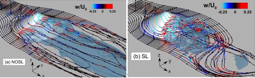
Instantaneous streamlines which originate from upstream are plotted at 𝑡∗ = 100: (a) NOSL and (b) SL. The streamlines are colored with the vertical velocity. The silver
blue color represents the isosurface 𝑢 = 0, which demarcates the recirculation zone behind the obstacle up to 𝑥∗ = 2.2 downstream.
|
Mean Streamwise Velocity |
Lee Vortices |
 |
 |
|
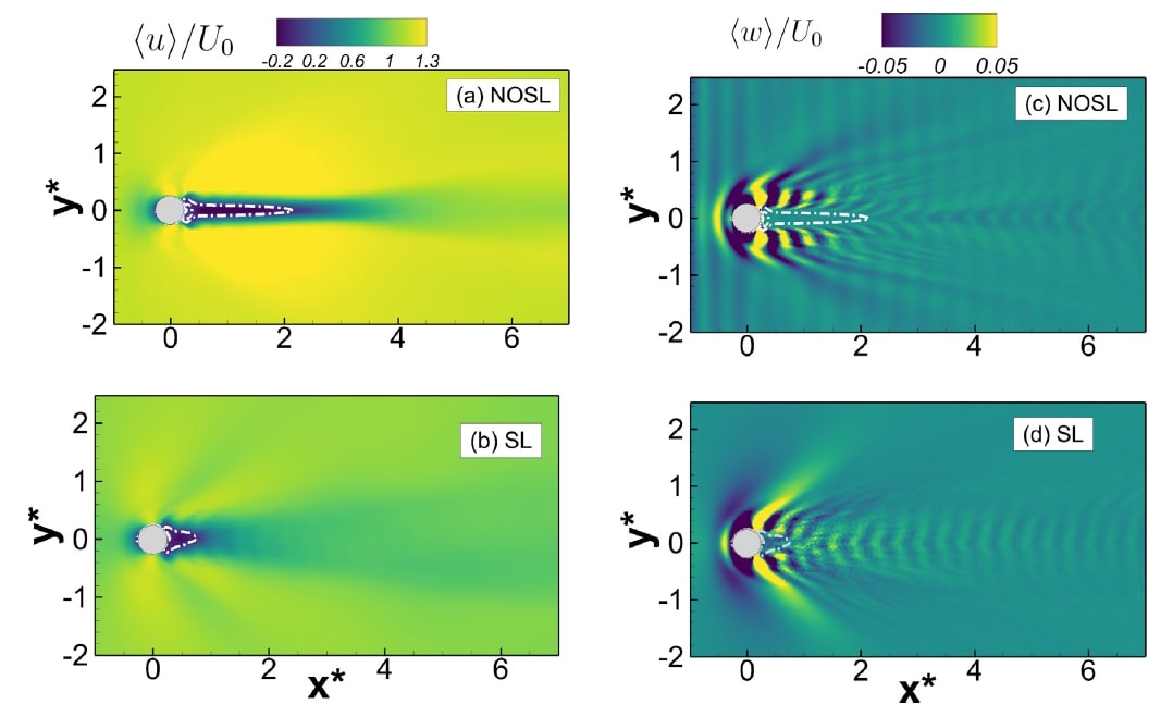
Mean streamwise velocity (a–b) and vertical velocity (c–d) in the horizontal plane 𝑧∗ = 0.5. Aspect ratio of figure axes is 1:1. The dotted white line denotes the 𝑢 = 0
contour.(b) SL. |
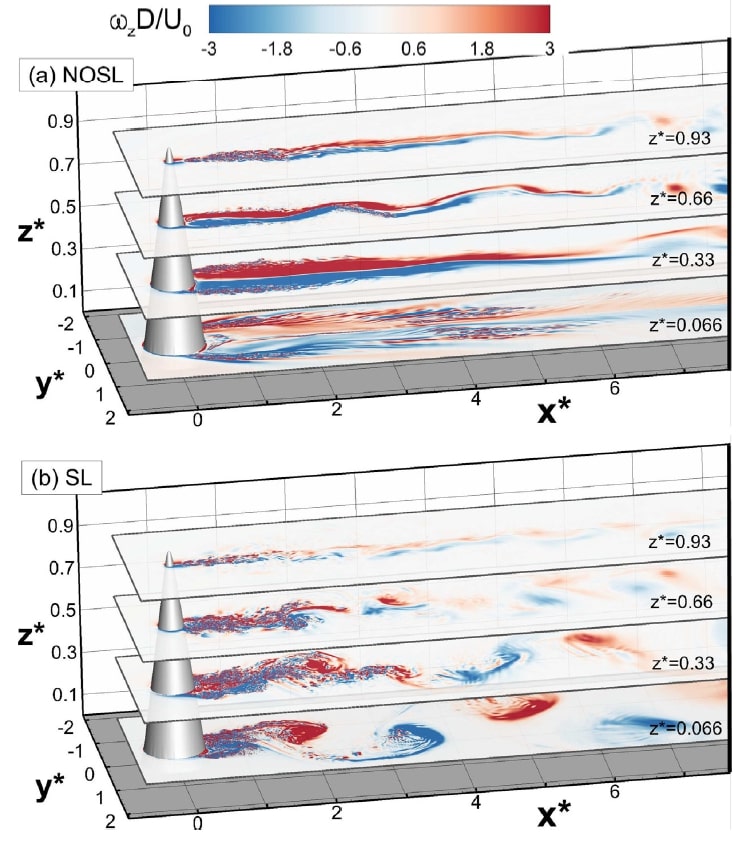
The organization of the lee vortices is affected by the boundary conditions. Lee vortices are shown by contours of normalized vertical vorticity at 𝑡∗ = 100: (a) NOSL,
and (b) SL. |
Density |
 |
|
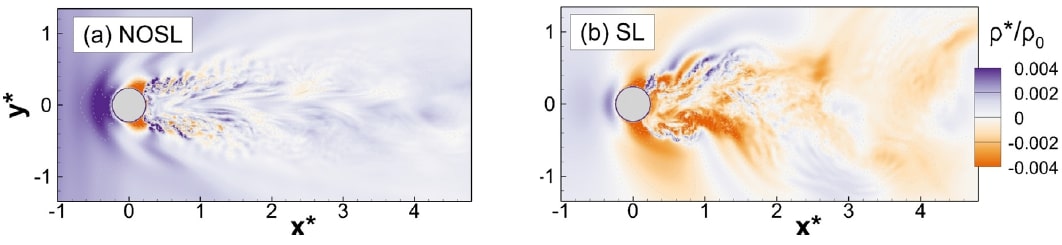
Streamwise and lateral gradients in density, visible from contours of the density deviation (𝜌∗) from the background, in the horizontal plane 𝑧∗ = 0.5: (a) NOSL, and (b)SL. |
© 2020 Sutanu Sarkar and the students of the CFD Lab